Learning To See - Simple Thinking
In this article I am going to give a snap shot of the application of simple thinking in a few examples. To gain a better understanding of how this is applied, I will be providing further details in September, via a short 'e-book', of how 'Learning To See' can be applied to Continuous Improvement activities such as problem solving, process management and problem prevention. If this is of interest please take a minute to sign up to the blogs to ensure you are notified of its available.
I have been using this phrase for some time to describe the learned discipline of being able to see things for what they actually are, without cluttering the facts with opinions and assumptions. Its about employing simple thinking.
This approach requires a degree of self-discipline in the first instance. However, it also requires a structured approach to many of the tools and techniques used in the management of business processes and procedures in any business.
There are five methods I use in my approach:
- Clear factual descriptions of problem, function and purpose statements
- Defining the boundaries of all activities
- Use of Visual Management to aid management and control
- Simple thinking
- Future State visioning
I will provide an overview of each of these, using simple examples to demonstrate
Clear Factual Descriptions
I commonly use two examples to explain the meaning, the first being problem solving and the second business development
We have a problem to solve, so the first step is to establish exactly what that problem is - this will be a clear statement detailing 'what is wrong with what'. All too often problems are not solved because we end up focusing on and dealing with the effect (the symptom), which masks the problem.
Business development often becomes just an increased sales effort, whether through increased sales activity, product development or looking to new markets, which in isolation often fails. Having a factual description of the business issue is the first step to creating an action plan that takes into consideration four main areas (SWOT) and provides an informed set of actions that can be directly addressed. This list will inevitably include some 'go find out' actions as well.
The SWOT analysis (you can download a free, editable template via the button at the bottom of this blog) is a detailed review of the business considering all of the strengths, weaknesses, opportunities and threats (or risks) that can be clearly articulated, using data and real information - in essence a clear description of where the business is.
Defining The Boundaries
Defining a boundary for any activity is an efficient way of ensuring time is not spent on things that are not part of the target activity. This may seem simple at first but it is all too easy to wander off in other directions, albeit for seemingly good reasons!
Visual Management
Visual Management is an integrated approach to supporting communication and information sharing, having visual messages may be part of something bigger.
In the 1980's the company I was working for signed up to a quality poster campaign.This involved lots of posters going up on site with a picture of a lion, bearing the legend "The Customer Is King" or a picture of a lovely, shiny, golden key stating "Quality is the KEY to our business" - so what? If the business processes and activities do not reflect these messages then what is the point?
Visual Management is about prompting the right reaction and should be tied into the business objectives and operating procedures and policies.
Simple Thinking
Clear, unclouded, focused, factual thinking. Recently I undertook an observation at a site, involving two guys who were themselves observing a complex activity. Their observation lasted about an hour and, in all fairness, copious notes were taken by both observers on what they saw, heard and experienced. My observation was of both them and the same activity they were observing.
When the observation session was complete we compared notes, I had a lot less written notes but had picked up on a number of issues that they had missed. So what was the difference? Both of the observers had entered the area expecting to see certain things, which was part of their preparation and plan for the observation event. I had deliberately avoided being told in advance anything about the activity we were to observe.
The two observers were looking for what they expected to see, whilst I saw everything as I carried no expectations for the session. I had no mental clutter, a clear understanding of what I was going to do and was dealing only with what I saw - the facts.
Future State Visioning
Future State Visioning is an important part of goal setting, having a clear visions is the first step to setting business or personal goals (or objectives). When coaching others to develop their goals I always ask if they use any form of visualisation and, as this is often seen as a bit 'fluffy', the answer is usually no. But if I ask the same people what they will be doing for the weekend, I can get them to describe the detail and even some of the emotions attached to that vision.....
Imagination (or creativity) plays a major part in successful goal setting and achievement. It has been said that the brain cannot differentiate between a real event and a vividly imagined one and we will all have experienced the emotions that imagination can provoke, both positive and negative. In goal setting we use our imagination to see what success would look like, feel like and even smell like!
I coached a Senior Team at a machine manufacturing company and we were looking at articulating their goal (to double turnover in two years). I asked them to consider all their senses in the context of this, what would the business:
Look like - would they be in the same physical space, what would the shop floor look like (more people, more processes, new products etc)
Smell like - new processes generate new smells, new products need new processes etc
Sound like - would the phone be ringing more, who would they be talking to, manufacturing sounds, process sounds, what new technology sounds would they hear
Feel like - kinasthetic feelings that come from new materials, new technologies and new processes.
The more detail we can imagine about our goal (future state) the more real we can make it and the more detailed your action plan will be.
It is said there is no such thing as luck in business, I disagree! luck is where opportunity and preparedness meet, therefore we need to be prepared to spot those opportunities. The better we can describe (or imagine) our goal, the more prepared we are to spot those opportunities.
Now you might be thinking what about this simple thinking stuff? For me this fits perfectly. Having a clear vision of a goal is the first step towards attaining that very goal.

Graham Cripps


 cannot design this pen to write on its own!


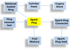
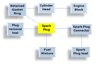
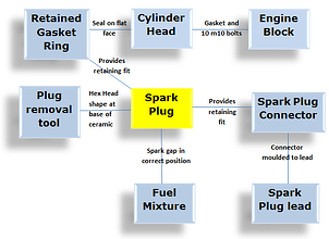
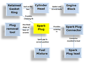 In this example I have suggested some linkages.
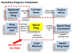
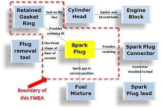
 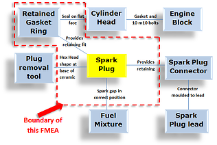 In this example the boundary diagram shows that this FMEA will include the spark plug assembly, the provision for retaining the spark plug connector, the provision for retaining the retained gasket ring, the retained gasket itself, positioning of the spark gap and provision of a hexagonal shape for the fitting and removal tools. However we won’t include the plug removal tool, spark plug connector, fuel mixture or the cylinder head in this FMEA.
