FMEA – A team based and structured approach
 Introduction
Potential Failure Modes and Effects Analysis (FMEA), or the analysis of the effects of failure of a design is used widely in the automotive, aerospace and associated industries.
A team based activity using an FMEA Template, Failure Mode and Effects Analysis (FMEA) is a risk management tool that, when applied well, can minimise the risk of failure of a product, process, service or design. FMEA is not a standalone quality tool it is supported by customer requirement input, customer usage data and other quality tools.
A completed FMEA is only the beginning. The output of the FMEA is an action plan to minimise the risk of failure in one or more of three ways: -
-
Minimising the severity of the effects of failure – the most difficult to do
-
Minimising the likely occurrence of the causes of potential failures
-
Maximising the detection or prevention of the failure mechanism (causes of failure) by providing data for design verification plans
A structured process, FMEA is often thought to be a difficult tool to use. However, where the design of a process, product or service has been well researched, documented and planned, FMEA builds on this knowledge and uses this data to consider all the risks associated with the use of the intended FMEA design.
The FMEA Template (or form - please see link at bottom of post)
Contrary to popular belief, the FMEA form does not drive the FMEA process, in fact the FMEA form has two specific purposes: -
-
To record and communicate the FMEA progress and outcomes
-
To record the action plan for, and the monitoring of, all necessary actions identified during the FMEA process.
The FMEA Process
There are 10 steps in the FMEA process. For the purpose of this article we will concentrate on the Design FMEA.
STEP 1 – Form the FMEA Team
The FMEA is carried out by a core team whose members are dictated by the subject of the FMEA and would include: Design Engineer, Process Engineer, Customer Representative (someone who has a clear understanding of customer requirements), and Quality Engineer. A support team is established to support the FMEA process as and when required and typically include: specialists; supplier representatives.
It is critical that the team includes at least one experienced FMEA practitioner to ensure the success of the FMEA activity.
STEP 2 - Determine Scope of the FMEA
An important step in the FMEA process is to set the scope of the FMEA (what will and what will not be included in this FMEA). If too much is included, then the FMEA becomes very time consuming and difficult to manage. This is one of the biggest reasons why FMEA’s often fail.
To determine the scope of a Design FMEA a Boundary Diagram is used. The boundary diagram is constructed from the design specification and should include the physical links or interactions between parts and sub-assembly levels. Also to be considered are the outcomes of the Robustness study. These linkages include considering the operating environment, interactions with other systems, customer usage (intended and unintended) and fatigue.
Once the boundary diagram has been completed and the scope identified, the composition of the team will need to be reconsidered to ensure all the necessary skills and knowledge are available to the core team.
Step 3 - Define the Product Design Functions (or Intent)
If we know all of the functions that a design has to achieve, then we can consider how we could potentially fail to meet the customer requirement. This is the key to understanding the exact functions that the product performs.
Example: We are to design a fountain pen. So what is a primary function of a pen? To write? Well, no. We cannot design a pen that writes on its own!
We have to consider our design inputs which might be: to retain ink, to dispense ink, to provide comfortable grip, to allow left and right handed use, to resist leaks, to facilitate smooth contact on writing surface etc.
We use a VERB-NOUN sentencing technique to describe each function. To dispense (verb) ink (noun). So a pen could fail to dispense ink. The user would experience failure to write, but this is the effect of failure of a prime function (this principle is explained later in this document).
It is very seldom that design specifications are written in this way so we use the Function Tree tool to capture and sort all the functions of a design from Primary functions to tertiary functions. To do this, the functions are brainstormed using the sentencing technique (described above). The Prime Functions are then identified from which we ask “how is this function achieved”. Using other functions brainstormed, the process is continued until an actionable level is reached (a level that could have a measurable attached to it based on the design specification). This is repeated for all primary functions. Then we ask of the tertiary functions why and moving back up the tree, providing the answer at each level, making grammatical sense throughout. See our separate article on the use of function trees.
Step 4 - Define Potential Failure Modes
Failure modes are often confused with the effects of the failure mode i.e. the toaster gave me a shock!. The failure mode is “fails to provide electrical insulation” where the shock is an effect of the failure. “Provide electrical insulation” is the function.
Failure modes are limited to just four main categories: -
-
Total Failure – the product fails to deliver the intended function
-
Partial Failure – the product fails to deliver all the intended function
-
Intermittent Failure – the product fails to deliver the intended function sometimes
-
Degraded Function – the product functionality degrades over time
There can be no other type of failure. Consider a domestic toaster. It can fail as follows:
Total – does not heat up or retain bread
Partial – heats up but does not retain the bread
Intermittent – sometimes takes three or four attempts to retain or heat the bread
Degraded – over time the toaster takes longer to brown the toast
All failure modes (the way the product fails to meet the designed intent or customer need) will fall into one of these four categories.
At this stage the Design FMEA process has a team established that are capable and knowledgeable to perform the FMEA and have a specialist support team identified. The scope of the FMEA and the potential failure modes have been identified and fully described.
Step 5 - Determine and Rank the severity of the effects of failure.
The effects of the failure modes are considered by the team in the following 7 categories: -
-
Part (subject of the design FMEA)
-
Assembly (the next level assembly that the part fits)
-
System (the system that this part contributes to)
-
Product (the overall product)
-
Customer (the user of the product)
-
Regulations (current legislation applicable in the country of use)
-
Other (any other category that may be industry or market specific)
The effects are recorded on the Design FMEA effects list (optional) and the FMEA form against the failure mode being considered. This will give a natural left to right flow across the FMEA record.
Each effect is now ranked in terms of its severity using the Design FMEA ranking tables. The highest severity is the one carried forward and recorded against the failure mode being considered.
Step 6 - Determine and Rank the likely occurrence of the causes of the failure modes
At this point we need to understand that the effect of the failure mode and the cause are not linked, other than through the failure mode itself. In other words, we are looking for the cause/s of the failure mode. The failure mode has effects that are experienced (sometimes called symptoms) as a result of that failure mode.
The team should brainstorm all the possible causes of failure. At this point it is important to note that we are confined to the scope of the failure mode of a specific function. Failure of the design to perform as intended. Therefore, mistakes that may be made during manufacture of the design can only be considered if they are as a direct result of design omissions.
Once the failure modes have been established, they are arranged in order against the failure mode on the FMEA form (a continuation of the flow established during the last process step).
Using the Design FMEA Ranking tables, each potential cause is ranked as to the likelihood of occurrence. The ranking is recorded alongside the cause in question. Because the use of ranking tables is not an “exact science”, the introduction of past experiences and other data is useful.
Step 7 - Establish and Rank all existing Design Controls
At this stage we are considering the existing design controls, this will include all those that are part of the current design and design verification processes. These controls may fall into one of four categories: -
-
Detection controls that will detect the cause of failure
-
Detection controls that will detect the failure mode
-
Preventative controls that will prevent the cause from occurring
-
Preventative controls that will prevent the failure mode from occurring
Once established, we use the DFME rating tables to rate how likely these controls are to work, the higher the number the less likely the control will work.
For example, if a design verification test does not consider or test for the cause (or failure mode), then this test will rate 9 or 10. If the test does consider the cause (or failure mode) and is such that it includes for the most demanding customer profile, then the rate could be 2 or 3 (ranking needs to consider the size of the tested population).
This process is repeated for all causes. In many cases, the causes will impact on more than one failure mode.
Step 8 - Calculate the RPN and establish priority of, and determine the actions required
As mentioned in the introduction, FMEA is a risk management tool and this and the next stage are all about minimising the risk of potential failures. We now have a record of: -
-
All the potential failure modes
-
The effects of failure for each failure mode and their severity rating
-
The causes of failure for each failure mode and their likely occurrence rating
-
The current detection and prevention design controls rated in terms of likelihood of detecting or preventing each failure mode.
Armed with this information we can now consider which of the failure modes is of greatest concern to the business. To do this we need to consider how we are going to prioritise them. To do this we calculate the Risk Priority Number (RPN). However, the RPN used in isolation can be misleading.
Results recommend the following approach when considering the priority of any required actions:-
-
High severity with high occurrence, form the obvious highest priority.
-
Other combinations will be driven by the company priority policy.
NOTE: in many cases it will not be possible to reduce severity therefore the focus must be on reducing likely occurrence.
Step 9 - Plan and implement improvement actions and establish revised RPN
We are now nearing the completion of the DFMEA process whereby the identified and agreed actions are to be planned and implemented. To this end, as well as throughout the FMEA process in general, we used the Deming P.D.C.A. Cycle (refer to your free FMEA Snap Shot Template)
|
PLAN – plan the implementation of the corrective or improvement action. These may have wide ranging impacts across the design and design verification processes. All actions should be comprehensively considered in terms of the likelihood of success.
|
DO – Carry out the modifications to the necessary design processes. This includes documenting the changes in all associated processes and reviewing test data outcome requirements.
CHECK – Carry out checks to ensure that the changes have taken place and are effective.
ACT - Take action on any advers results
Step 10 - Close the DFMEA process
The Design FMEA has now been completed for the chosen design function or design intent. However, the FMEA process cannot be considered complete until all the final closing actions have been taken. These include: -
-
The DFMEA has been fully completed and all actions closed out.
-
The question log has been fully closed out
-
All lessons learnt have been recorded and communicated
-
All processes now reflect the new agreed standards
-
The FMEA Champion is fully aware of the outputs from the DFMEA
-
All core and support team members’ contributions have been formally recognised.
-
The complete DFMEA includes all documentation raised during the process including: -

Graham Cripps
Results Consortium Ltd
 Having formed the FMEA team you now need to determine the scope of the FMEA.
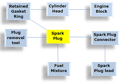
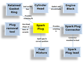 In this example I have suggested some linkages.
 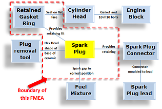 In this example the boundary diagram shows that this FMEA will include the spark plug assembly, the provision for retaining the spark plug connector, the provision for retaining the retained gasket ring, the retained gasket itself, positioning of the spark gap and provision of a hexagonal shape for the fitting and removal tools. However we won’t include the plug removal tool, spark plug connector, fuel mixture or the cylinder head in this FMEA.
 In this short series of articles I will be sharing with you the steps to applying FMEA successfully as well as some handy tips to ensure you do not fall foul of the top six reasons FMEA's fail to deliver the required outcomes.
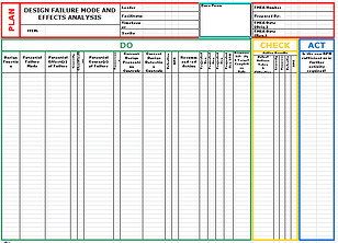 The Results FMEA template provides for a record of the FMEA team members and this shoud be completed at the end of the first meeting along with the target item details etc.